Tag Archives: Antenna

A V/U Handheld Moxon Antenna for Satellites

The Completed MoxonAs per my last post, I have been getting pretty excited about working satellites. However relying on the little ‘rubber duck’ antenna that came with the IC-T90A hand held does limit the range in a way that I could only really work the satellites at high elevation angles. With costs of commercial V/U antennas for satellite work usually over $200 AUD, it was time to build my own.

I did have some constraints around the antenna design:

  • It had to cost under $50 to make.
  • No speciality materials required – I could either readily purchase from a shop, or I already had materials on hand.
  • It had to be made using tools I had on hand.

The last point ruled out making a crossed yagi antenna to my standards as it would require a drill press to successfully fabricate (I am bad at drilling square!)

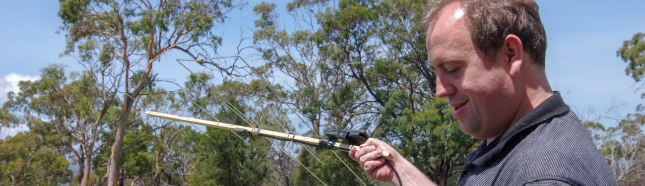
In the end a quick google found me looking at making a Moxon designed by LY3LP and modified by M1GEO, but I really wanted to get some close ups of some of the more important parts of the build. What follows is an abbreviated build guide with photos. In all, it took less than 2 hours to construct.

Update 22/12/2018 2.15pm – Yep, this antenna is a winner – here is the audio from the AO-91 pass @ 2018-12-22 1342 AEDT. Big improvement – action starts at around 2mins in.

Continue reading

Experiments with an End Fed Half Wave Antenna

Portable Setup, Mount Direction

Portable on Mount Direction

I went away to the Tasmania’s West Coast in October 2016 and had hoped to work some stations. For radio, the trip was a bit of a disaster with the place we were staying having lots of solar inverter noise. The other thing was that it was very tedious to use a linked dipole in the location I was in. Since that day I had resolved that I would try and end-fed antenna and see how that goes.

The End Fed Half Wave (EFHW) antenna is popular with many QRP Portable stations, particularly for activities such as SOTA or WWFF. The big drawback of the end-fed is the high impedances they have, which means that you need to carry some sort of Antenna tuner to match the impedance with the radio. The thought of lugging around an antenna tuner and then having to retune every time I switched frequency was less than appealing though.

Continue reading

Building A linked Dipole

IMG_1989It’s been a little while since I have posted, and its not because I haven’t been doing anything. I’ve been getting my portable station even more portable that before. Ov er the past 3 weeks where I have had a spare evening I have been putting together a new portable station that is even more lightweight than the previous setup featured in my post on Peter Murrell Reserve. Key to this has been producing a linked dipole.

Linked dipoles provide the benefit of creating a single-wire antenna that is resonant on multiple bands without a tuner by “linking” together lengths of wire with clips. While there is no limit on how many links you make, it may not be practical to make the dipole suit everything between 1.8 and 450 Mhz.

I ended up going for a 5 band antenna – 6m, 10m, 15m, 20m, 40m.

Continue reading

Letting the Smoke Out I

Oops

Above is a rather fine example of letting the smoke out. My last post talked about replacing a dipole that had worked well for many years but suddenly not so much. With the options of breaking it all apart to check the inside pieces, or throwing out the antenna, I chose the former.

What you are looking at is a very cooked load. Originally 9 10k ohm resistors in parallel are now well in truly charred. behind this (as evidenced by red winding wire) is a ferrite rod with a coil wrapped around it, in parallel with the resistor bank. These loads are used to give the antenna its low SWR across all bands.

Cooking the loads occurs when you forget there is a difference between Px and Py power and also forget that most baluns/loads can take a greater amount of the former over the latter. In this case my new radio allowed me to transmit 100 watts of PSK31, when the antenna was only rated for 50 watts.

It’s not out of the realms of possibility to repair this, should the ferrites in the loads and balun still be in working order. However when you take into consideration that I am would probably need to replace most of the stainless steel wire, obtain replacement resistors and still end up with a balun of questionable integrity (due to aforementioned power excesses), it may be time to recover what I can from the antenna and throw out the remains.

New HF Antenna for Home – an OCF Windom!

OCFWindom

When I made up the 4:1 balun earlier this week, I didn’t realise that I would be putting it to use by the end of the week!

Ever since I got active again, the commercial multi band dipole that I had been using for many years was no longer working optimally. When I first purchased it, it had an SWR of < 1.8:1 across most bands, but recently the SWR had had risen to around 2.5:1 across most bands. After discussing and troubleshooting the issue with the antenna manufacturer, it was decided the cost to replace faulty parts exceeded the original purchase price of the antenna.

It was time to replace the antenna.

Continue reading

Building A Balun

Testing the Balun with 200 Ohms and an Analyser. Looks good to me!

Testing the Balun with 200 Ohms and an Analyser. Looks good to me!

Baluns have always been a bit of a homebrew boogeyman to me, mainly due do what appeared to be some sort of magical winding technique around a toroid. However, given the prices of baluns these days seems to range from $60 AUD upwards, given I have all the parts already at home to make one (“free”), I decided to bite the bullet and learn how to make one.

I’m not going to bore you with the details on how a balun works here, other than to say I think they are useful for connecting coax to antennas. Ladder line, while more efficient, doesn’t have a very good use-case for my applications and good quality ladder line is also expensive and difficult to obtain compared to the plenty of coax I already have available to me.

Shout out to VK6YF whose diagrams for the 4:1 Ruthroff voltage balun were what I used. Some people will be quick to tell me that it was odd to make a 4:1 balun when I am not using ladder line – I agree (and in hindsight should have made a 1:1 balun), but this was about learning how to make a balun.

You can imagine my surprise after being having my build peer reviewed by my good friend Murray that other than a dry joint that was soon fixed, the balun actually worked! to put this in context, two previous attempts at building a balun had resulted in wildly varying SWR and resistive load that on the whole didn’t look much better than just using a piece of wire.

Anyway, now that I know I can build them, I will obtain another jiffy box to build a 1:1 balun for use with my upcoming portable dipole!


Back on 6m

6m Dipole

6m dipole finally in the air

I’m finally back on the 6m band. It wasn’t a cakewalk, with the dipole generally un-cooperative with the element parting ways with the Acro-bat insulator, and then finding the masthead pulley rope (pictured to the right in the photo) was no longer going up to the masthead, meaning that I needed to lower the mast to replace it.

1:1 coax balun made by VK7ZIF is the centre-feed, and I took the time to redo the PL259 connectors and waterproof them prior to reinstalling to make that particular joint a lot stronger than last time. It was this joint that led to the antenna’s demise a few years ago.

Plugged in, and tested, works a treat with low SWR, which was how I remembered it.

I’m looking at building a new and improved version of this antenna at some point using 2mm multi-strand stainless marine stainless steel wire, much the same as my HF dipole.