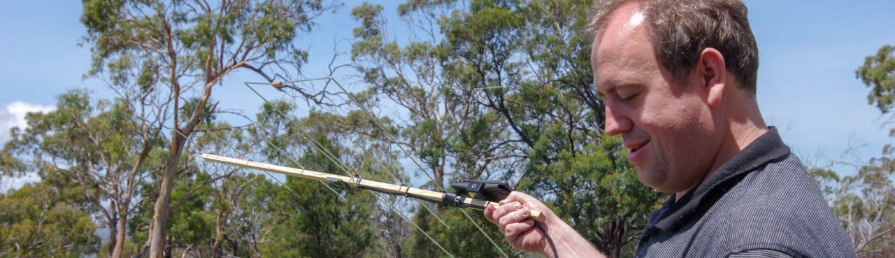

It’s been a couple of years now since my first post on EFHW Antennas. Notably since then I have acquired a Mini 600 Analyser. Armed with technology it was time to revisit this “no-tune” portable antenna. What followed was 3 months of confusion, learning and experimentation.
Before I go any further I would sincerely like to thank David VK3IL for his patience and assistance over the last 2 weeks in helping me troubleshoot my issues and teach me a bit more about what I was doing along the way.
It all started when I thought it would be a good idea to re-test the end-fed antenna now I have a new analyser as I was preparing ready-to-assemble kits for my local radio club and didn’t want to see people ending up with an antenna that didn’t work as described. To my dismay, the antenna definitely was not working as originally described.

The Antenna wasn’t looking that hot – SWR @ 40m was around 1.26:1, and was already above 2 on 20m. This was not the same readings as when I last used the antenna. the Vk5JST analyser that I used prior back up the Mini 600 readings.
It was about this time that the Analyser took a tumble from a low height and despite there being no physical damage to the unit, it would no longer operate – screen would power on but the code on the STM would no longer run.
Damnit is the politer way I putting the language I used. Everything went on hold for 4 weeks until a new analyser was acquired.

Being a practical sort, I felt the best way test would be to build a second matching unit, this time using a genuine FT140-43 (and not the Jaycar Branded LO1238), along with a smaller gauge winding wire to make a bit easier to wrap around the toroid.
Assembled and ready to test, I went back outside and set up, only to find a minimal difference! I am pretty damned sure it’s built right, and having replaced all the components has ruled out component fault. It was time to get some help. I emailed Dave, VK3IL.

After doing some initial checks, there was some thought it may have been the compensation capacitor (hence the use a different ceramic). All this checked out and Dave then suggested I test with a known impedance by placing a 3.3k ohm resistor between the feed point and ground.
Bingo. first bit of success. The SWR plot from this looked very much like what was to be expected on the VK3IL website.
This means that the matching unit is working as it should. If it’s not the matching unit, there’s only 2 other things it can be – the feed line, or the antenna itself.
” I’m guessing you may have a break in the wire somewhere. One of the challenges in portable antennas is finding a wire that will cope with repeated winding and unwinding”
DavID, VK3IL
I was sceptical. The antenna wire tested ok with continuity, but I wasn’t ready to rule out it being a minor fracture that only manifested itself when the wire was stretched out under it’s own gravitational weight when I had it set up.
AWG 22 wire is not easy to obtain locally and I was loathe to break into my precious supply for kits. Initially I was thinking wire trace used in fishing, but the stainless steel would be an issue. What I did end up using was 1.2mm braided steel picture hanging wire found at Australia’s favourite hardware and sausage-in-bread store, Bunnings.
Picture hanging wire is not coated, and therefore faults are easy to see. Picture hanging wire is also a pain to use as it is prone to twisting up and kinking as I quickly found out.
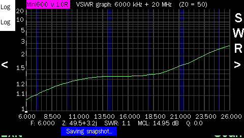
All said and done though, the results seemed promising:

Comparing the grey baseline of a well matched load, the graphs showing the SWR rise as the frequency increased made sense. Additionally, it would appear that the blue steel braid had more reduced SWR peaks than the AWG 22 wire. Unfortunately though there was very little difference in the SWR for matched frequencies. This rules out the antenna wire being the issue.
Around this time, I was also playing with installing a small tuning capacitor to replace the fixed value 150pF MLCC in the match box. This made a significant difference to the tuning ability of the matching unit and I found on 20m, I could get SWR down to 1.05:1 with 85pF and on 15m down to about 1.7:1 with 50pF and a little bit of elevation. This did get the antenna matched enough to be usable, however I didn’t want a complication of having to tune the match box.
This only left one thing left to change – the feed line, which was also acting as a counterpoise. The only thing longer than 4m I had was 25m of LMR195, so that was what I used. And with this I hit the jackpot:

Pink – AWG22 with 25m LMR195 – Grey – Tested 3.3k ohm load
As can be seen in the above charts, significant reductions in peak SWR again, but also 3 bands are now usable (and half of 10m!). A win in this test is SWR < 2.0:1.
Usable Frequencies (SWR < 2.0:1), AWG22 Wire
- 6.750Mhz – 7.350 Mhz
- 13.8Mhz – 14.8Mhz
- 21.00Mhz – 22.250Mhz
- 28.90Mhz – 30Mhz
Lessons Learnt
- That the feed line and antenna element should never be discounted as part of a fault just because they are “only wire”.
- The external environment such as elevation, ground type and angles are critical to measuring an end fed when close to ground. Taking David’s advice the match unit was kept close to ground, as this is where you would typically deploy it in a “sloper” configuration.
- A tuning capacitor would be a fine modification to this antenna if you did want to fiddle more with tuning in the field. I may investigate this further.
- Trust my builds 🙂 as it turned out, both matching units gave nearly identical measurements, which were verified as OK.
Even More Experiments with End Feds?
There is definitely more to come. While troubleshooting, I came across more information, including making a 40-20-10 trapped end fed that is around 12m in length – 40% smaller! Having small, portable antennas is really appealing to me so I will definitely be looking into this.
I found your original article quite inspirational. I’ve just constructed one of these beasties with a Jaycar toroid and 20m of something labelled “ClotheSline” that was purchased for $3 from one of those little homeware/hardware/giftware shops. It seems to be about 3mm multi-strand steel wire in a thick vinyl covering, and meant for use as a portable clothesline. Bunnings have a 30m length of 4mm clothesline wire for about $6 on their site, but I haven’t been in store to check it out yet. They’ll both be a lot heavier, but they’re probably a lot more manageable than picture hanging wire. The wire I used came with plastic hooks so it could be hung up as a “ClotheSline” and I use one of these as the end of the antenna – folding back rather than cutting, so I can adjust the length on site if/when required. An 8-10mm bend radius at the hook where the wire turns back on itself helps avoid kinking.
Thanks for your Comments Mark! I am glad you felt inspired to make one of these – ununs and baluns used to be a dark magic thing for me that you would sacrifice a goat and things happened until I had a go at actually making one.
Clothesline is definitely fine to use – a little bit overkill for portable/SOTA operations though. I tend to use a linked dipole more than the EFHW just because many locations it is easier to have a centre feed up high on the squid pole, rather than trying to find a suitable location to string a longwire. Out in field I just use AWG22 🙂
Hopefully I will get to work you on air one day! enjoy!